Step 1 — PlayStation 3 Slim Teardown
·
It's here! We got our dirty hands on a
PS3 Slim a full day before it was set to arrive in the mail!
·
The box, just like the unit, is, well, slimmer.
·
Did you know you can post your own teardown on iFixit? Share what's inside your gadgets! Take apart an old cell phone,
microwave, or toy robot.
o
We host everything for free, and make it
easy for you to have high-resolution photos, professional layout, and
full screen slideshows like ours!


Step
2
·
Along with the PS3
Slim you get:
o Sixaxis DualShock 3 controller
o RCA Cables
o USB Cable
o Power Cord
o QuickStart Guide and Instruction Manual
o Welcome to PS3 and PS Network Blu-ray Disc
o One of those "Guide to Video Game Ratings" guides that
nobody gives a [redacted] about.


Step 3
·
On the front left we
have two USB ports, a hard drive indicator light, and a Wi-Fi indicator light.
·
Front right yields a
slot-loading Blu-ray drive, power button, and eject button.
·
The back has a LAN
connection, HDMI port, digital audio-out, multi-connector (RCA or component
video) and a new type of power plug.
·
Owners of the
current-gen PS3s will notice an absence of the rear manual power switch. All
your powering needs are now served by the front power button.


Step
4
·
Now that we've
dispensed with the pleasantries, let's get into the meat of the subject, so to
speak.
·
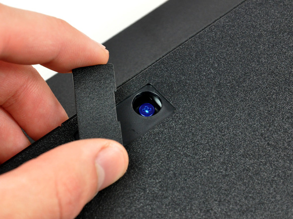
We start with the
hard drive first.
o A blue Phillips screw is hidden beneath "the blue Phillips
screw cover," as we call it. Remove this screw.
§ You can view this blue Phillips screw in all its glory if you'd like.
o Next, remove the hard drive cover.

Step
5
·
The drive enclosure
has a metal pull tab attached to it. Pull on it to release the drive from the
bay.
·
The 120 GB Toshiba
drive, in all its glory. We have a feeling that it's going to be super-easy to
upgrade this drive to 500GB...


Step
6
·
Remove the three T8
security Torx screws on the underside of the PS3 slim.
·
What's that, you say?
Security screws? Yes, that's right. These screws have a pin in the center of
them that prevents an ordinary Torx screwdriver from working. These
screwdrivers are widely available, just not quite as easy to come by as a
normal Torx.
·
Sony did this to
prevent people like us from taking it apart.
·
Those three T8
security Torx screws seem to be the only non-Phillips head fasteners on the
entire device.
·
This seems a little
spiteful-- hardware hacking is a fine American tradition. No worries, we'll make
sure it's easy for you
to get these screwdrivers.

Step
7
·
De-warranty-izing and
de-tabbing on the underside of the Slim ensues...
·
If you haven't seen
them already, check out our dozens of teardowns,
ripping apart everything from a cappuccino
machine to an iPhone
3GS.


Step 8
·
Seven Phillips screws
need to be removed from the bottom.
·
Interestingly enough,
the rubber pad on the front-right corner of the PS3 has no screw hidden
underneath it. Imagine our surprise when we removed it!

Step
9
·
Flip the PS3 over.
·
Wait for it, wait for
it...
·
MEGA FAN revealed!
·
This 12V, 1.3A
monster rivals the best fans found in desktop PC machines. Sony spared no
expense.


Step
10
·
Closeup of the
massive fan and controller antennas.
·
This is a brushless
DC motor, which is fairly standard for fans in devices like this. Brushless
motors are quieter than more traditional fans, but require fine computer
control to function. It is not a maglev fan like Apple is known to use,
however.
·
The Bluetooth and
WLAN antennas, intentionally three-dimensional in design, are attached to the
lower case with Phillips screws.


Step
11
·
Disconnecting two
power supply cables.
·
The AC inlet cable is
devoid of a third 'ground' pin, surprising for a unit that draws nearly 250W.


Step
12
·
Removing the power
supply. This is quite a bit smaller than the original PS3's power supply, and
presumably has better thermal characteristics.
·
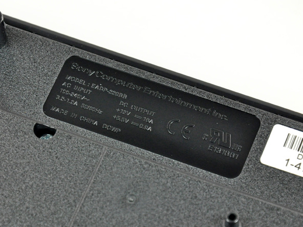
Much to the relief of
users worldwide, the power supply is designed for inputs ranging from 100V to
240V AC.


Step 13
·
Digging a little
deeper into the new power supply.
·
This is a startlingly
compact unit. It will be interesting to see what the thermal dissipation is
like.
·
This puppy cranks out
18 amps at 12V DC! Fingers beware.


Step
14
·
This is the largest
fan we've come across in a consumer electronics device of this size.
·
Sony is really taking
cooling quite seriously.
·
The ~95 mm diameter
17 blade impeller was definitely designed with quiet in mind. It is extremely
stiff and presumably made of ABS plastic.


Step
15
·
Tape holding down
antenna and power cables.
·
That tape is just
begging to be ripped off.
·
We indulged.


Step
16
·
A tug at the plug, a twist
of the screwdriver...


Step
17
·
The Blu-ray drive
comes right out.
·
This drive is still
quite large, and takes up the bulk of the space inside the PS3.
·
We disassembled the
drive, and found that it appears to be a proprietary Sony-manufactured part.


Step
18
·
More connectors and
screws to unplug/unscrew.
·
The design aesthetic
of this machine is quite a bit more bare-bones-functional than Apple's, but is
still beautiful in its own way.
·
Several components,
including the AC power inlet, are simply held to the unit by the pressure of
the screws connecting the top and bottom cases.


Step
19
·
A few more screws,
and the logic board lifts free of the chassis!


Step
20
·
Unscrewing several
screws securing the EMI shield.
·
The two identical
matte finished brackets in the first picture are designed to apply pressure to
the center of the processors, keeping them firmly planted on their heat sinks.


Step
21
·
Separating the metal
electromagnetic interference shield from the logic board.


Step 22
·
The whole [slim]
enchilada!
·
Counterclockwise from
the left:
o Power supply, main board, hard drive, EMI shield, heat sink,
fan, Blu-ray drive, controller, and plastic case.
Step
23
·
That's it for the
disassembly, but we'll continue to post board photos and analysis as the
information pours in.
·
The logic board.
Sony's going green on the inside, to reflect their commitment to the
environment. ViewHUGE version.
·
We've never seen cool
snowflake-like patterns in the thermal paste after we removed a heat sink
before. This may indicate that the thermal paste was overapplied or that it was
not distributed evenly.
·
If you look closely
at the thermal paste, you'll see it is a fractal!


Step
24
·
The Cell processor
looks very spiffy under our lights.
·
We didn't think it
was possible to synthesize reality, but the RSX chip (from an Acura?!) proves
us wrong.
·
Chip labels: RSX
Reality Synthesizer CXD2991EGB 0916HFZ 114477


Step
25
·
Multiple
manufacturers, multiple functions. The first picture shows two of the four
NEC/TOKIN 0e108 capacitors.
o NEC/TOKIN Corporation creates "next-generation,
value-added devices that integrate." Whatever that means.
o High Speed Decoupling Device Proadlizer PF/A SeriesProadlizer
PF/A Series.
·
Dual Elpida 512Mbit RAM chips (there are four
total on the board).
·
The third picture
shows, from left to right:
o Marvell Ethernet controller
o Panasonic HDMI controller
o Sony AV multi-out controller


Step
26
·
But wait -- there's
more!
·
Clock generators from left to right:
o Clock generator (1): ICS 9249AGLF
o Clock generator (2): ICS 1493DG
·
Samsung
K8Q2815UQB-PI4B
·
SW2-301 0920KMOOT
·
Sony CXD9963G8


Step
27
·
We put the latest
iPod Shuffle on top of the processor. The shuffle is just slightly longer, but
the overall area of the processor is vastly larger.

Source : http://www.ifixit.com
No comments:
Post a Comment